HOME > ASSEMBLING INSTRUCTION

|
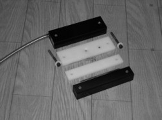
Step 1: 1) There must be one switch, two spacers and one actuator magnet. 2) Do not remove the actuator keeper yet. 3) Decide which type of fasteners are appropriate for the installation. 4) It is useful to anticipate the switch and actuator alignment before proceeding. The gap spacing as well as the switch actuator alignment must be within specifications. |
|
|
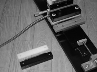
Step 2: 1) Drill holes for the switch and spacer which fits under the switch. 2) Fix the spacer to the stationary frame with a flat head screw ensuring that the small anti-tamper magnet is to the right as shown. 3) The spacer may be used as a template for the holes. 4) Sometimes, double sided adhesive tape can facilitate the assembly procedure, although it should be removed before fixing the spacer. |
|
|
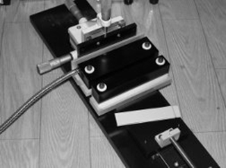
Step 3: 1) Fix the switch to the stationary frame using appropriate fasteners with the cable to the left as shown. |
|
|
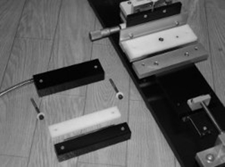
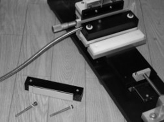
Step 4: 1) Drill holes for the actuator and spacer which fits under the actuator. 2) The holes must be placed so that face of the actuator is 0.25 inches from the face of the switch ( a 0.25 inch gap). 3) The spacer can be used as a template for the holes. 4) Sometimes, double sided adhesive tape can facilitate the assembly procedure, although it should be removed before fixing the actuator. |
|
|
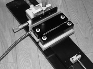
Step 5: 1) Fix the actuator and spacer using appropriate fasteners to the movable member or door. 2) Ensure that the top surfaces of the switch and actuator are aligned. If the surfaces do not align, a thicker or thinner spacer may be required to ensure that they do align. 3) It is easier to fix the actuator without removing the keeper during installation; especially on steel doors.
|
|
|
Step 6: |
 |
|
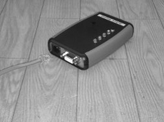
Step 7: 2) Turn ON the tester. 3) The Green light should turn on momentarily. 4) The Red light should turn on for one second while the switch resets and initializes. 5) The Green light should turn on and remain on. 6) If the Green light turns on only for one second and switches back to Red, check the installation for proper switch and actuator alignment. This is normal, if the door is open. 7) Pressing and releasing the remote test button will automatically repeat this test. |
|
|
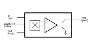
Step 8: 2) The existing high positive line should be connected to Vout (green). 3) Most security systems have 12V lines going to other devices. This 12V power line and ground can form part of this installation. The remaining existing switch ground line just determined and the 12V power ground line should be connected together with the switch Gnd (black). 4) The 12V power line should be connected to Vs (red). 5) The switch yellow wire is connected to Remote Test. Many systems have a remote test feature. A 12V pulse on this line will reset the switch and cycle it through the test sequence in Step 7 above. This is an optional step. Leaving this Remote Test line open will not affect the switch function or operation. |
 |