
JRM1212
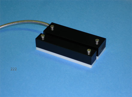
3D Balanced High Security Magnetometer Systems Features • 3D Balanced Magnetometer • Invulnerable to any Defeat Key • Class A EMI and Lightning Suppression • UL 634 Level 2 Standards • NEMA Rating 1,2,3,4,4x,5,6,12 • RoHS Compliant • Open Collector Output • Remote Test • Anti-tamper • No Electrical Contacts • Insensitive to Vibration or Shock • Reversed Battery Protection • No Gap Hysteresis • Solid-State Reliability • All Climates Category Description This 3D Triple Balanced High Security Device, is the only known intelligent 3D Magnetometer security device. The complex shape of the magnetic field surrounding the sensor and permanent magnet actuator is analyzed by advanced proprietary algorithms to detect defeat attempts. The air gap or space between the actuator and the sensor array is designed to prohibit defeat. False alarms are eliminated by Class A EMI suppression filters and inherent immunity to shock and vibration. Anti-tamper is built into the device which requires the supplied spacers. It can be wired into existing BMS/HSS systems as replacements for passive devices, provided polarity on the open collector (Vout) is positive.
|
Absolute Maximum Ratings Supply Voltage ............................................................ +18V Collector-Emitter Voltage ........................................... +35V Output Average Forward Current............................. 50 mA Storage Temperature.......................................-55°C to 125°C Operating Temperature Range ...................... -40°C to 125°C |
|

Operational Characteristics
|
PARAMETER |
CONDITIONS |
MIN TYP MAX |
UNITS |
|
Supply Voltage |
over temperature range |
7 12 18 |
V |
|
Actuation Gap Maximum |
with 1/4 inch spacer |
0.40 |
inches |
|
Actuation Gap Minimum |
with 1/4 inch spacer |
0.20 |
inches |
|
Power Line Current |
Supply Voltage = +12 |
150 |
mA |
|
Maximum Output Current |
all supply voltage conditions |
50 |
mA |
|
Secure Output Level |
actuated |
0.1 |
V |
|
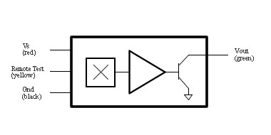
Applications Information General The magnetometer uses DSP to detect the magnet actuator status. It is designed to operate from the standard 12Vdc security network power lines. The sensor output is open collector for voltage level translation. The output is pulled low in a secure state. The alarm state occurs by default if power is removed from the device in an active security system. Remote test is automatically conducted when power is applied to the device and may be conducted at any time by placing a 12V pulse on the remote test line. |
Extraneous Field Susceptibility
The device is insensitive to high frequency magnetic fields such as those generated by transformers and electric motors. Low frequency magnetic fields, such as those generated by permanent magnets in the vicinity of the device are interpreted as an attempt to breach the security system and generate an alarm state. All inputs and outputs have Class A EMI suppression filters which also provided a measure of protection against lightning. |
Simplified Schematic
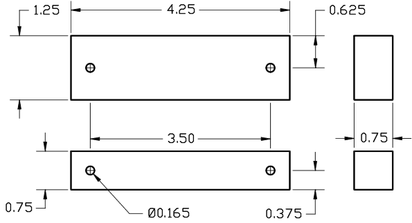
Package Description (INCH)
Output Cable
|
The output cable is an armored four (4) conductor telephone cable one meter long suitable for RJ11 connectors. |